
Switches for industrial environments are designed to fulfill a crucial purpose: ensuring the reliability of…
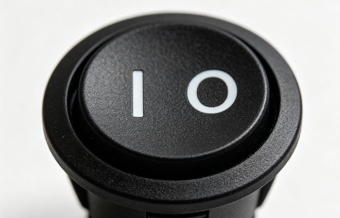
What exactly do the I, O and II symbols on a switch mean?
The I, O and II symbols on a switch appear on countless electronic devices. Their purpose is to indicate the power status without relying on words or any particular language. Yet despite their widespread use and simple message, they are often confused, and misreading them can leave both the user and the device unprotected.
What are the origin and meaning of the I, O and II symbols on a switch?
The I and O markings originate from binary logic. The first represents the presence of a signal, while the second represents its absence. Applied to electrical circuits, I indicates a closed contact, allowing current to flow, while O indicates an open contact, with no power flowing. The O is a zero, not a letter.
The International Electrotechnical Commission (IEC) includes these markings in the IEC 60417 series, which covers graphical symbols for equipment. The aim is to standardise their use among manufacturers in different countries. A word such as “on” requires translation and takes up more space, whereas a vertical line and a circle do not. They also fit easily on small push buttons and selectors.
The standby symbol—a broken circle with a vertical line extending into it—combines both markings. It indicates an intermediate state in which the equipment remains partially powered. Thanks to the simplicity of these symbols, M2B’s electronics technicians use this convention to check at a glance whether a section of an electrical circuit is energised before working on it.
The function of position II in multi-position switching systems
When a switch offers more than two states, the labelling expands accordingly. The II marking identifies a second active position, distinct from I. Depending on the device’s design, the control moves between O, I and II.
Three devices illustrate its uses. On a fan or heater, I usually corresponds to a low setting and II to a high setting. On a power transfer switch, I connects one power source and II another—for example, the mains supply and a generator. On a machine tool, each active position selects a different operating mode.
Position O is usually located in the centre of the switch’s travel, keeping the two sources isolated from each other. This arrangement prevents two power supplies from feeding the same equipment simultaneously. Before handling the device, check the manufacturer’s technical data sheet, as the exact meaning of II may vary between models.
Some models add a third active position, III, or a locking mechanism that allows the control to be padlocked in position O, which is useful during maintenance. Each position must be clearly and legibly marked on the control or housing.
Understanding the I, O and II symbols on a switch is therefore a basic requirement for operating any installation safely. I closes the circuit, O opens it, and II provides a second operating option. For advice on selectors, changeover switches or control panels, visit M2B, where we offer professional technical guidance.
Related Posts

