The current market shows a clear trend: vandal-proof switches are no longer reserved exclusively for…
Exactly What Do the I, O and II Symbols on a Switch Mean?
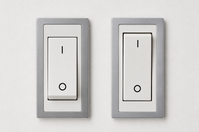
The I, O and II symbols on a switch make it possible to quickly identify its different operating positions. In general, I indicates ON or connection, O indicates OFF or disconnection, and II identifies a second operating position on certain multi-position switches or changeover switches. The specific function of II always depends on the electrical design of the component and the equipment in which it is integrated.
M2B Technologies is a company specialising in the design and manufacture of switches and electromechanical components for electrical and electronic equipment manufacturers. With more than 40 years of experience, its products are designed and tested in Barcelona and subsequently manufactured by its Asian industrial partner according to M2B specifications. The company supplies switches, indicator lights, assemblies and customised solutions for national and international projects. (m2bswitches.eu)
Correctly understanding these markings is especially important for engineering, purchasing and production departments that need to select and integrate switches into machinery, control panels and electrical equipment.
What do the I and O symbols on a switch mean?
The I symbol normally identifies the ON or connection position, while the O symbol identifies the OFF or disconnection position.
This marking is covered by international standards on graphical symbols for electrical equipment. IEC 60417 identifies symbol 5007 as “ON (power)” and symbol 5008 as “OFF (power)”, providing a common reference regardless of the user’s language or the country in which the equipment is used. (IEC)
When a switch is set to I, the equipment or function associated with the switch is normally activated. When it is set to O, that function is deactivated or the disconnection defined by the device design takes place.
Although I and O visually resemble the binary values 1 and 0, from a technical point of view it is more accurate to interpret these symbols according to their standardised ON and OFF functions.
Furthermore, the O position of a control should not automatically be considered a guarantee of complete electrical isolation. The level of disconnection or isolation depends on the characteristics of the switch, its contact architecture and the requirements applicable to the equipment.
What does II mean on a switch?
The II symbol usually identifies a second active position or a second function on a multi-position switch, but its specific meaning depends on the circuit in which it is integrated.
Unlike I and O, II should not be interpreted in isolation as having a universal electrical function.
On an I-O-II selector or changeover switch, for example, the three positions can be used to select between two circuits, two power sources or two operating modes, with O acting as an intermediate OFF position.
Electrical equipment manufacturers use I-O-II configurations precisely in transfer switches and devices designed to switch between two sources. ABB, Eaton and Schneider Electric document this type of configuration in different product families. (Schneider Electric)
A configuration could therefore be:
- I: first source, circuit or operating mode.
- O: OFF or disconnection position.
- II: second source, circuit or operating mode.
However, this interpretation should always be checked against the technical data sheet, electrical diagram and contact configuration of the selected switch.
Examples of uses for an I-O-II switch
A three-position switch can be used in many different applications.
For example, it can be used to select between a main and an alternative power supply, choose between two operating modes of a machine or control different functions from a single actuator.
In industrial applications, there are also I-O-II changeover switches specifically designed to transfer between two electrical sources while maintaining an intermediate O position. (ABB)
For this reason, II does not necessarily mean “more power” or “second circuit” in every type of equipment. The final function is determined by the electrical architecture designed by the manufacturer.
Why are standardised symbols used on switches?
Standardised symbols make it easier to quickly recognise the status and function of a switch without depending on the user’s language.
This is particularly relevant for machinery, industrial equipment, electrical appliances and control panels used in different markets.
IEC 60073 establishes general principles for coding indicators and actuators in human-machine interfaces, while IEC 61310 addresses indication, marking and actuation systems related to machinery safety. (IEC)
For an equipment manufacturer, clear markings can help to:
- Facilitate identification of the different control positions.
- Reduce errors during equipment operation.
- Simplify the design of products intended for international markets.
- Improve consistency between the switch, panel and technical documentation.
- Facilitate installation and maintenance work.
What should be checked in addition to the I, O and II symbols?
The symbols alone are not enough to determine whether a switch is suitable for a specific application. Its electrical, mechanical and environmental characteristics must be checked before selecting a component.
The main criteria include:
- Rated voltage and current.
- Number of poles and contacts.
- Switching diagram and function.
- Number of positions.
- Type of actuator.
- Dimensions and mounting system.
- Mechanical and electrical life.
- Required degree of protection.
- Environmental operating conditions.
- Certifications required for the product or target market.
For three-position applications, checking the contact diagram is particularly important, as it shows exactly which terminals are connected in positions I, O and II.
The importance of switch markings in industrial equipment
In a component that will be integrated into machinery or mass-produced equipment, the legibility and durability of the markings are also part of the product design.
The symbols must remain identifiable throughout the intended service life of the equipment and be suitable for the conditions of use. Factors such as frequency of use, cleaning, contact with certain substances or environmental conditions may affect which marking solution is most appropriate.
This becomes particularly relevant when a manufacturer needs to develop a customised switch for a specific application.
M2B Technologies: switches and electromechanical solutions for manufacturers
M2B Technologies designs and manufactures electromechanical components for electrical and electronic equipment manufacturers, with products designed and tested in Barcelona. Its catalogue includes rocker switches, push switches, micro switches, metal switches, rotary switches, slide switches, power sockets and indicator lights.
In addition to supplying components, M2B can support its customers from the design stages through to production, including switches, indicators, assemblies and customised solutions.
For projects requiring a specific configuration of positions, contacts, actuation or customisation, the component should be selected according to the electrical diagram and actual application specifications, rather than solely on the basis of the symbols visible on the actuator.
Explore the assemblies and custom hardware solutions from M2B Technologies or contact its technical team to determine which switch and configuration best suits the requirements of your project.
Frequently asked questions about the I, O and II symbols on a switch
What does I mean on a switch?
I normally indicates the ON or connection position of the switch. IEC 60417 identifies this symbol as “ON (power)”. Selecting this position activates the electrical function defined by the equipment design.
What does O mean on a switch?
O normally identifies the OFF or disconnection position. In IEC symbology it is used to represent “OFF (power)”. The specific electrical effect depends on the device design, so the symbol alone should not be taken to mean that all circuits are fully isolated.
What does II mean on a switch?
II usually represents a second active position of a selector or changeover switch. It may correspond to a second source, speed, circuit or operating mode, but there is no single function applicable to all equipment. The switch diagram must be consulted.
What is the difference between an I-O switch and an I-O-II switch?
An I-O switch normally has two positions, while an I-O-II switch has three. In the latter, I and II may control two different functions, with O acting as an intermediate OFF or disconnection position, depending on the electrical design.
Do I and O mean 1 and 0?
The symbols visually resemble the digits 1 and 0, but technically they should be interpreted as the standardised indications for ON and OFF. For engineering specifications, it is more appropriate to use their functional meaning according to the applicable standard.
Do all I-O-II switches work in the same way?
No. The I-O-II marking identifies actuator positions, but the corresponding electrical connections may vary. Before integrating a three-position switch, its technical data sheet, number of poles, contact diagram and switching configuration must be checked.
How do you choose an I-O-II switch for an industrial project?
It should be selected according to the electrical and mechanical characteristics of the application. Voltage, current, contact configuration, number of poles, mounting, environmental conditions, required service life and certifications applicable to the final equipment must all be considered. M2B Technologies can assess switch configurations and electromechanical components for manufacturers’ projects.
Related Posts